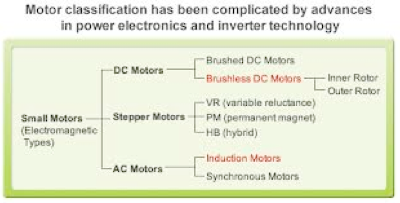
One of my running pals, Nathan, loaned me a book about electric motors, which caused me to seek more knowledge about types of motor. Most classifications start with the distinction between AC and DC and power source, and while this is the most common, that does not necessarily make the best first choice.
An electric motor converts electrical energy into mechanical energy. In most cases the mechanical energy drives a rotating shaft. The fundamental effect required can be distinguished by a simple enough experiment: Place a rectangular plate of various materials on a lubricated surface and observe the effect of moving a strong magnet past the plate. For example, use rollers on a table and move the magnet beneath, sharply in one direction. (i) a good insulator (ii) a perfect conductor (iii) a good conductor (iv) a ferromagnetic substance, such as iron.
Case 1: a good insulator. Nothing is observed. Theory suggests there may be some temporary transient charge changes, but no gross movement.
Case 2: a perfect conductor. Nothing is observed. Theory suggests that a perfect conductor (think superconductor) will not permit the penetration of any currents induced by a time-varying magnetic field.
Case 3: a good conductor, such as copper or aluminium. The plate will move in the direction of the motion of the magnet. It may need a brisk movement of the magnet to begin motion. There may be some noticeable delay in the effect. Accepted theory says the magnetic field induces eddy currents in opposition to the moving field. Confusion occurs in identifying this as a push or a pull from the experiment.
Case 4: a ferromagnetic material such as iron. The sheet moves in line with the magnet; the plate pushes down towards the magnet; there is no delay or lag; small movement of the magnet is matched by the plate.
For precision, we use the word motor to indicate that electrical energy in => usable mechanical energy out. The reverse machine is a generator. Some machines are capable of doing both, giving us useful facilities such as engine braking and regenerative braking. There are devices such as loudspeakers and solenoids that produce motion, but these are not called motors. A transducer turns energy from one form to another (loudspeaker, from electrical to sound; lamp bulb from electrical to light, antenna, from radio to electrical). An actuator is the general term for a device that turns energy into motion; the same term describes turning linear motion into rotational, turning signal into motion. An actuator may be powered by a motor, so in essence the term actuator refers to the control system - which might be human intervention. So the test of motor is the production of usable mechanical energy, which means something more like an ability to cope with having a load applied.
I’ll conform with the sources I found and start by separating by power source, despite the confusion it causes, so as not to rock the boat so early that you stop reading.
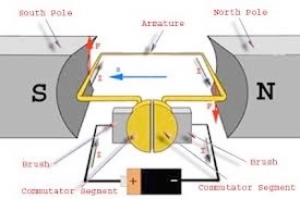
A DC motor¹ consists of three principal components, stator (at rest, stationary so usually closely allied with the armature), rotor (the moving bit) and commutator (the connector between the two, particularly the electrical connection).
The practical problem with the DC motor as shown is that when the rotor coil is positioned vertically (90º from as shown) there is no reason for it to move. If it is moving, then it will continue to move by inertia. The commutator is generally in contact with the brushes, which adds friction. Where there is a small gap there can be sparkling across the gap, which will damage both surfaces, so leading to maintenance issues. Sparking also produces radio interference, which in the modern age is an issue to avoid. To avoid the rotor sticking in its ‘rest’ state, several loops of conductor at different angles are used in the rotor, with corresponding complication in the commutator. In turn, that leads to opportunity to use current chip technology to reduce complexity (effectively, the complexity moves into the control circuits), which provides all sorts of gains – basically, better machines needing less maintenance. Additional notes below³,⁴.
One type of DC motor is a stepping (or stepper) motor: this is brushless and divides a rotor cycle into steps by using pulsed input. A typical stepper motor will have a toothed rotor, where each tooth is magnetised (permanent, coil, iron only, hybrid). All stepper motors require (some fairly clever) control circuitry. These can be very precise motors. More phases means less vibration. There is a wide variety of these motors, including constant voltage and constant current. There is no necessary assumption that the number of rotors matches the number of stators, nor should we assume that the wave-form is perfectly sinusoidal or perfectly square.
AC motors
The stator magnets can be electrical coils around ferromagnetic poles, which allows for rapid switching up to the limits of the materials’ capacity to change magnetic state. Thus we have the useful distinctions of a motor being synchronous or asynchronous. In a synchronous motor, the shaft rotation is an integer number of AC cycles. The many stator poles are paired electromagnets; the rotor poles will be permanent magnets of electromagnets. The rotor steps in line with the switching speed; putting that another way, at the design speed the rotor rotation is locked to the rotating magnetic field. This means the motor has a precise and consistent speed, making them ideal for timers and other precision devices. It also means they need a starter winding that turns off as they near design speed.
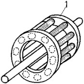
An induction motor is asynchronous and AC. The current in the rotor is induced from the magnetic field of the stator winding(s). It does not (therefore) need a commutator or excitation. The rotor will be wound on a squirrel cage (see foot of page). Large induction motors will use 3-phase electricity, though there is not reason not to have multiple phase supply. As with the synchronous motors the magnetic field rotates in synch with the AC cycles. For induction, though, the rotor goes slower than the stator field. Effectively there are two windings one inside the other; the magnetic fields oppose each other (Lenz’s law: the magnetic field created will oppose change of current in the rotor windings) so the rotating stator field induces current in the rotor windings, so the rotor will chase until it balances the load. the ‘slip’ between stator cycle and rotor cycle is typically 0.5-5%. If load is added, the rotor speed drops momentarily which adds to rotor current and therefore adds torque, so its speeds up again.
Modern electronics provides facility to vary the cycle frequency of the power supply, making induction motors now suitable for variable speed applications. Note also³ that when the rotor speed is caused to be higher than the stator field speed, the motor acts as a generator.
A so-called universal motor can be powered by AC or DC. All universal motors are commutated series-wound motors. Series-wound means the stator field coils are connected in series with the rotor coils through the commutator. Universal motors are light, compact, run at high speed and have a high starting torque; because they have brushes, these will show wear and so the universal motor is not suited to continuous use. Thus we find them in hand-held power tools and household appliances⁵.
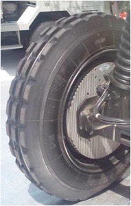
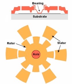
I wondered if there was any reason other than convention for the stator to be on the outside. Of course not: that is what you need for an in-wheel (hub, external rotor) motor. I liked what I found at Printed Motor Works and added here a picture of their XR 32-13 hub motor inside the wheel of a military electric vehicle
Linear motors are AC asynchronous induction motors. They usually run on 3-phase power; they are used where contact-less force is required or where low maintenance is an issue (having no moving parts). I found a persistent description as this being a rotary motor cut open and laid flat. There must be end effects of unrolling a circle. See essay 161. Wikipedia tells us that there are two general classifications:
low acceleration such as mag-lev trains (and other ground-based transport systems), which are mostly linear synchronous motors, the magnets on one side of the air gap and the coils on the other.
Picture in red, green and grey nearby.
high acceleration, meaning mass-drivers, spacecraft and weapons (railgun, coilgun). These two weapon systems are different: A railgun⁶ uses a homopolar design requiring paired rails with or without a travelling armature (think a tray to sit a load upon). These are a long way from repetitive use, but for doing things such as throwing robust loads into orbit, would be cheap compared with our other launch systems, perhaps 40 times less. A coilgun⁷, possibly using multiple coils, accelerates a projectile within the coil. The projectile may be ferromagnetic but not necessarily so, since the projectile could include a coil and / or the projectile could be a conductor. What may be called hobbyist examples exist and the earliest examples of linear motor weapons are a century old already.
I found several tables similar to the one given at the top, some of which were quite complicated, but none of which struck me as complete. I suspect a lot of the problem is that there are so few binary (black and white) divisions. Synchronous/asynchronous, but AC/DC doesn’t work unless we also allow combinations (AC & DC). Linear/rotary is a possible distinguishing mark. Size gives distinctions, as does the power input, but several motor labels, e.g. induction, would occur more than once. I will work on this some more – maybe I can be clear enough to do this. I doubt it, since so much of the labelling is not so much conflicted as insufficiently unambiguous. It appears that if you want a motor you really should specify what it is required to do (be able to do) and then go find something to fit the specification.
DJS 20150520 (17th-20th and 28th)
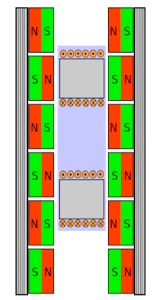
In red and orange is a picture of a micro-motor. Many of these have differing numbers of stator poles and rotor poles. the control mechanism provides pulsed voltage across opposing stator poles, and there is no commutator, partly because the gap between stator and rotor is a micrometre or two. This might be called a variable capacitance motor.
DC machines can be made brushless by using an integrated switching power supply, giving a bi-directional alternating current (not necessarily sinusoidal, either). This to me, renders the DC label confusing. A brushless machine is more expensive to make but lasts longer with less maintenance (higher reliability). In consequence they are found in myriad small-load and small-size situations.
1 DC= direct current, distinct from AC, Alternating current, which includes multiple phases, usually 1 or 3.
2 The armature may BE the stator. An armature must carry current; it carries current across the field to create torque or linear force and it generates electro-motive force (EMF).
3 When a dc motor has mechanical power applied to the shaft, it acts as a generator. There are (solved) issues with the control circuitry and so we have regenerative braking, such as is found on railway systems. To make this happen the operator needs to be able to vary the frequency of the power supply to the motor AND, since the braking effect falls away at lower speeds, a friction brake is still required. If you consider engine braking in a car on a slippery surface, you soon discover you need to slow the non-drive wheels too. Obviously regenerative braking is a very good thing in terms of conserving energy (it is moved to another form for use later). An example of intelligent design (my opinion) is where London Underground lines have slopes up to and down from stations; energy is stored as gravitational potential energy, regained on exiting downhill from the station. Dynamic brakes change the excess energy to (waste) heat. The issue with regenerative braking is that the generated power must match the supply quite closely. Some braking can be used to fill other constant needs, such as heating / cooling systems on trains. Progress has been made with the use of flywheels as temporary stores of kinetic energy, being tested in F1 motor sport in 2009 and from 2011 onwards. As yet the flywheel is more efficient than generator/battery systems.
4 The physical size of the brushes means that they can be touching two commutators at once, which shorts the circuit. While brief, this is still not good and to avoid that state requires a gap between commutator rings similar to the size of the brushes. what is important is to avoid induced voltage in the shorted commutator loop (I read: I don’t understand what to do about that. My conclusion was that alternative motors would be better).
5 The converse is also true: the majority of motors in the home are universal motors used intermittently. Non-universal motors inside the home would be would be brushless dc motors found perhaps in fan and disk drives (in your computers, printer, DVD player, CD, etc). You might have a linear motor in your sewing machine; a stepper motor in your watch and clocks and your printer. You might just have an axial rotor motor.
6 Railguns are attractive as weapons because they remove explosive from the launcher. To be effective they must be very strong, as the forces tend to distort the rails. Speeds are very high (>Mach 5) so they are attractive as ship-mounted weaponry. To launch guided missiles we need the missile to survive the launch process. The unit of measure becomes MJ, the energy given to the projectile during firing / launch, or the energy in MJ delivered on missile impact. For context the 16 inch guns used on ships at the end of WWII delivered 360MJ and 160MJ downrange (typically half), using large rounds that need machinery to lift. These exploratory weapons are typically larger but fire a smaller round far more often, each with energy delivered downrange of a similar order to a 5 inch gun. 10-30MJ seems an appropriate size at the moment, where range could be > 150 km on a 10 kg round. Guided rounds require the guidance system to survive the firing process, which will be difficult to develop. Another difficulty is power supply, where firing rate depends upon spare capacity. Assuming a rate of say 6 rounds per minute, a load of 10kg will need around 30MJ, for which the required power is 25MW, far more than is typically available. No, I can’t make sense of those figures, I’m quoting.
7 Coilguns (Gauss rifles) are build-able and portable and you should expect that any exploration of this trips some over-watch. They’re less robust and more complicated than rail guns. A hobbyist gun will deliver joules (say 1-30 J) so it compares with an air rifle. Possible advantages are no smoke on firing, though a sonic boom is still likely. Barrels could be surprisingly short – I found a mortar design only 120mm long with double the firing rate of the conventional design and a third more range. That’s hardly bigger than my hand. Sci-fi theorists suggest fairly large coilguns for firing supplies to orbit, such as to L5 from the Moon – very cheap delivery.
top pic from http://www.renesas.com/edge_ol/features/04/index.jsp
References:
http://www.electrical4u.com/working-or-operating-principle-of-dc-motor/
very small motors: http://pubs.acs.org/doi/abs/10.1021/cr400273r http://www.berkeley.edu/news/media/releases/2003/07/23_motor.shtml http://www.nanowerk.com/nanotechnology-news/newsid=37601.php discusses replacing copper in the windings by or with carbon nanotube yarn, at least twice as conductive as copper and dramatically lighter. Sell your shares in copper mining.
http://www.ece.umn.edu/users/riaz/animations/sqmovies.html animated induction motor.
On regenerative braking, http://en.wikipedia.org/wiki/Regenerative_brake and note the first such was in 1886.
pancake motors http://www.printedmotorworks.com
On linear motors wikipedia and http://machinedesign.com/linear-motion/difference-between-linear-motors-and-linear-mechanical-devices
A synchronous machine must be AC.
Synchronous motors come in ‘excited’ and ‘non-excited’ types, each with a steel rotor. Excited means there is current supplied to the rotor. Non-excited rotors are made of steel in three types:
reluctance (toothed rotor poles, needs a starter circuit)
hysteresis (smooth cylindrical rotor, constant lag behind stator field, so constant torque and a self-starter)
permanent magnets (fixed into the rotor, not a self-starter)
the fourth, excited form, has DC current to the rotor (it’s still AC to the stator) through slip rings or by induction, even possibly generating the DC current from from the motor shaft.
These are used for larger scale motors, above a kilowatt.
Large synchronous motors are not self-starting because of the inertia of the rotor. Most solutions to this is to add a so-called squirrel cage (pictures) induction winding. Very large motors will have an engine to wind them up (a ‘pony’ motor). Sophisticated controllers can start form zero by changing the stator current frequency. Synchronous motors might also use three-phase power.