

An atom that gains electrons has more negative particles and is negatively charged [an ion]. Electrons can be made to move from one atom to another. When those electrons move between the atoms, a current of electricity is created. So says a teaching resource in California.
I am prompted to write about this as the boss, my wife, is teaching early Physics and has a load of questions. Nine-year-olds ask good questions and I found I didn’t have good answers. So here I will find and share some better answers, I hope.
So if electrons are persuaded to move between atoms, what makes them do that? Why does it happen more easily in some materials than others? How fast does electricity go? Is a conductor ionised, and if so has it changed state somehow?
To so many of this type of question the best answer is “We don’t know”. When that happens, we invent words to describe the condition, but finding out the ‘why’ stretches our theories, often to breaking. Indeed, ‘why’ is rarely answered, but a description of what (we think) happens can be found. Does that answer ‘why?’ I am not sure it does.
Why is copper a good conductor?
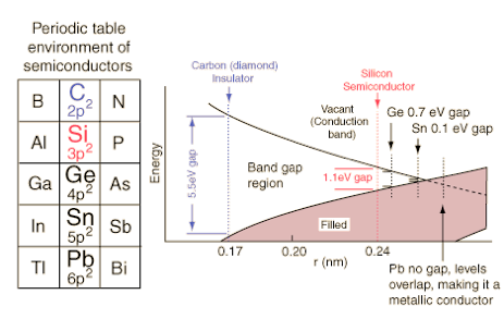
A material that allows electrons to be displaced easily is a conductor, which in turn means it provides little resistance, which we can measure. Thinking for the moment of solid conductors, metals make good conductors, especially copper, silver and gold. Why them? Secondary school science refers to bands or shells of electrons. The outermost shell is called the valence band and the space just inside that is called the conduction band¹. If (when) these two bands overlap then electrons can easily be displaced (i.e. flow) and we have conductivity. So this means we have redirected the answer to “Why is it a good conductor?” from ‘Look how low the resistance is’ to ‘Go measure the gaps between the energy bands’. Which we can’t at home or at school.
0.138 10⁶/cm Ω Cadmium Cd 48
0.139 10⁶/cmΩ Potassium K 19
0.143 10⁶/cm Ω Nickel Ni 28
0.166 10⁶/cm Ω Zinc Zn 30
0.172 10⁶/cm Ω Cobalt Co 27
0.187 10⁶/cm Ω Molybdenum Mo 42
0.189 10⁶/cm Ω Tungsten W 74
0.197 10⁶/cm Ω Iridium Ir 77
0.210 10⁶/cm Ω Sodium Na 11
0.211 10⁶/cm Ω Rhodium Rh 45
0.226 10⁶/cm Ω Magnesium Mg 12
0.298 10⁶/cm Ω Calcium Ca 20
0.313 10⁶/cm Ω Beryllium Be 4
0.377 10⁶/cm Ω Aluminium Al 13
0.452 10⁶/cm Ω Gold Au 79
0.596 10⁶/cm Ω Copper Cu 29
0.630 10⁶/cm Ω Silver Ag 47
Moving on from the frustration there, let’s imagine we can go ask questions about this, ‘band theory’ ². We have the ability to measure energy bands for the outermost electrons.
The texts I found are more interested in semi-conductors, such as the diagram above. Copper, silver and gold belong to the left of these on the periodic table, one above the other, which suggests that their positioning optimises the likelihood of conductance. The columns left and right (zinc, cadmium, mercury; nickel, palladium, platinum) are presumably also good conductors.
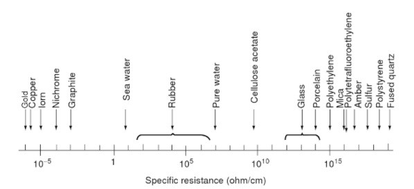
Checking that, I found a list of elements in order of conductivity, left; this indicates that the matter is more critical than one might expect and indicates Aluminium as a choice—given its comparative abundance, a good choice. The left column measures conductivity in reciprocal ohm centimetres, called siemens per centimetre.

Using these units, bigger is better; more conductivity. Wiki, to which I just donated again, tells me that carbon (as graphene³) is even better, at 1x10⁶ S/cm [1x10⁸ S/m]⁴
How fast is electricity? The drift velocity of electrons (in a solid across which is applied a voltage to as to cause a current, meaning movement of electrons) is low, around a metre per hour (wiki), but the apparent transmission is at the speed of light. The theory says this is like the balls in Newton’s cradle (pic to the right); nudge one at this end of the line and the one at the other end falls off. I’m going to call that signal speed.
Further hunting for answers gave responses between 1% and 50% of light speed. There is quite a deal of confusion over what it is we are talking about and there are (the result of the usual muddled and muddied research) three speeds to consider, which A-level Physics students might already know:
the speed of an individual electron. If there is no electric field then electrons are whizzing about hitting atoms and we might measure the speed of the movement between collisions. We could call this heat in the wire. Light speed, c, is 3x10⁸ m/sec; individual electron velocity is roughly c/1000.
drift velocity . When there’s an electric field the electrons are more organised about the direction of travel and we call this the. Drift velocity is measured in metres per hour, centimetres per second. Slow.
signal velocity; the effect of one electron moving upon another far away is much sooner than the other two speeds, which I am happy to call the signal speed⁶. Signal velocity is more like c/10, between 10⁸ and 10⁹ kmph. For diversion you might research the range of signal speeds, to see how close to c they might reach⁸. Try reading about velocity factor⁷, which suggests that signal speed could be much closer to c. The signal speed depends on the dielectric constant of the material, presumably an indirect measure of how close together the electrons are.
I found a good deal of confusion when trying to answer “What is the speed of electricity?”, many of which are really measuring electron drift. Electrons do have mass, so transmission must be slower than light—is that confusing electron drift with signal speed? The speed of electricity is better described as the rate of flow of charge, which is proportional to the current, so that means that anything less than the least complicated circuit has several speeds at the same time. Charge goes faster in a thinner wire (think of water moving to a narrower pipe); a change of material (say from copper to aluminium) changes the speed of flow. For A-level students, you might want to read about the ‘charge-sea’. This site was useful.
Why are some wires bigger? Conductivity, inverse resistance, is J/E, amps per square metre divided by volts per metre. Thus the J (current density) is changed by the wire size; thicker wires have lower resistance. [Pouillet’s Law says resistance varies with length over area, implied by my statement.] The voltage will drop along the length of a wire and a wire has a current capacity; this is a limit determined by how hot you will accept the wire becoming. If a wire is getting hot, you should replace it with something bigger (thicker, not longer). How to calculate this? I found loads of helpful calculators but the theory behind this was elusive. I found that resistance changes with temperature, generally going up; a hotter wire has more resistance and will therefore get hotter still.
One of the issues (thanks to Paul Martin for the additional material) is that surface resistivity and volume resistivity are different. The first is where electron flows through the material (and obviously that is dependent upon the material composition, don’t assume it is necessarily a solid) and the second along the surface, which is dependent upon things like surface roughness and films (think oil and water) attaching to that surface.. Paul’s site explains quite a bit of this. His interest is primarily in using plastics as insulators. I copied this useful diagram on the right. As he observes: a highly polished surface adds to the resistance; resistance drops with increases in temperature or humidity (though that is much reduced by water content in the material, as in wood). I also note that if using a composite material such as a filled foam these inevitably change the resistivity, perhaps significantly; look up doping of semiconductors. I do not understand why volume resistivity goes up (or why it changes at all) the longer the voltage is applied; that suggests to me that in some sense there is an effect opposing the electron flow that increases with time. It also implies that this resistivity returns to some previous value when the flow is not applied. Which suggests that some materials make unreliable resistors. Weird.
Why do you I have to have a load on a battery? How does the battery ‘know’ how much to put out?
How is a battery used up? The chemistry stops working; the battery is an energy store and it will become empty. For dry cell batteries, All batteries contain one or more cells, but people often use the terms battery and cell interchangeably. A cell is just the working chemical unit inside a battery; one battery can contain any number of cells. A cell has three main parts: a positive electrode (terminal), a negative electrode, and a liquid or solid separating them called the electrolyte. When a battery is connected to an electric circuit, a chemical reaction takes place in the electrolyte causing ions (in this case, atoms with a positive electrical charge) to flow through it one way, with electrons (particles with a negative charge) flowing through the outer circuit in the other direction. This movement of electric charge makes an electric current flow through the cell and through the circuit it is connected to. It's important to note that the electrodes in a battery are always made from two dissimilar materials (so never both from the same metal, for example). This is the key to how and why a battery works: one of the materials "likes" to give up electrons, the other likes to receive them. If both electrodes were made from the same material, that wouldn’t happen and no current would flow. (apparent source)
This looks like a quote but I didn’t put it in brown when first publishing & don’t know why that is so on editing this in 2018. I took the first sentence, put it in quotes and shoved it into Google. The number of hits suggests plagiarism abounds. One such match, which looks complete, was here.
Why can’t I put batteries in parallel? You can. Three 1.5v batteries in parallel will last three times as long as one battery. Life is measured in amp-hours, but that is, it turns out, not a terribly helpful predictor of how a battery will behave in use. The same three batteries in series (connected end to end) will give 4.5V for the life of one battery (the weakest of the three).
Which way round does the current go? Electrons go from negative electrode, -ve, to the positive electrode, +ve, repelled by the -ve pole of the battery, attracted by the +ve pole. The convention is that current goes from +ve to -ve, the opposite direction. Way back when this stuff was being discovered (not invented) a choice was made; they were wrong, but they didn’t know about electrons then. The result is we call it conventional current flow and it is the opposite way to the electron flow. That’s an answer to “Why is it confusing?”—they got it wrong; think of it as measuring the movement of positive particles, not negative ones. So it doesn’t matter where you put the on/off switch in a circuit. Tradition says you cut off the conventional flow, so the switch will usually be found on the positive side of the circuit, near the power source.
What is grounding? In principle, grounding connects objects which conduct electricity (but may well not be deliberately in a circuit) to the planet so as to reduce the difference in charge and therefore to eliminate static charges.
The term ground is (mis-)used in car electrics and electronics to mean the common return path for a number of circuits; ‘common’ is a far better term for this. In radio the grounding of an antenna is an important feature worthy of attention, research, and even employment.
Does it matter which way round I put the battery? In simple circuits, it won’t make a difference. Some components, such as transistors, need it round one way and not the other. So the test is, does this circuit have any electronics (circuit board stuff). If yes, then it matters. Physically, with batteries the connectors work best the ‘right’ way round, the big spring going to the base. Batteries are marked +ve and -ve at the ends and so is the equipment you want to use (where the battery goes in). What you can’t sensibly do is put chains of batteries with some reversed; that is counter-productive (they’ll cancel out in terms of voltage) and you’ll just spoil the batteries.
Why do you want to talk about parallel circuits?
Because then we can have different current to different gadgets. If we put a heater and a light in series the light doesn’t want very much current and that will determine (why?) the circuit current, so the heater won’t work at all well.
What’s different about A/c?
In terms of how wires work, it seems that the current travels (more) along the surface of the wire, so a/c cable is made of many thin wires to make lots of surface. Further confusion arises because with a/c impedance takes over from resistance. Complicated, literally. Smart 9-year old question: does that a/c sort of current make a light flicker, only very quickly? ⁵
Big power lines aren’t copper; why?
Overhead power lines are made in aluminium for two reasons; cost and weight. For the same conductance, the aluminium is lighter (although 58% thicker for the same conductance, Al is 48% of the resistivity density (the product of resistivity and density). Resistivity (nΩm); Cu 16.78, Al 26.5: density (g/cm3); Cu 8.96, Al 2.70. We might find some worthwhile sums to do to justify the swap to Aluminium.
Relevant Theory:
Ohm’s Law says V=IR. Voltage (volts) is current (amperes, amps) times resistance (ohms). Resistance does not change with the current. Kirchoff’s version of this is J=σE: current density, J, amps per sq metre; conductivity, σ, siemens per metre; and electric field, E, volts per metre (and newtons per coulomb); all at the location considered.
In school conditions using batteries, it would be typical to have a fixed voltage in multiples of 1.5V.
Example 1: Suppose we have a 3V supply and a 100Ω resistor with effectively two smaller resistances in the connecting wires (we can look up the resistance in tables, so let’s say we have two lengths of 2.5Ω); Ohm’s law says the circuit current I=V/R = 3/(100+2*2.5) = 3/105 = 28.57mA.
Across one of our two wires, the voltage drop is V=IR = 0.02857*2.5 = 71.4mV. Similarly across the load resistance V=2.857V=2857mV, so our total voltage drop across the circuit is 3V, a nice check.
Power is current times voltage, P=VI so each of our two connecting wires is using 0.1176*0.0294=3.457mW
Parallel circuits; Theory, supported by empirical measurement, says the current is the sum through each resistance; the voltage is the same across each parallel circuit, because this is as if we have joined three separate circuits at the supply terminals.
Example 2: Suppose we have a 3V supply and three 100Ω resistors ignoring the resistance of the connecting wires. Each resistance demands 0.03A, total current 0.09A, voltage drop across any one resistance is 3V.
Example 3: Suppose we have a 3V supply and three parallel resistors, 50Ω, 100Ω, 150Ω ignoring the resistance of the connecting wires. Each resistance, r, demands 3/r amps, total current therefore 3(1/50+1/100+1/150) = 0.11A, voltage drop across any one resistance is 3V. Thus the total resistance is worked out with reciprocals: RTotal⁻¹ = R₁⁻¹ + R₂⁻¹ + R₃⁻¹ + …
DJS 20151201
really, Tuesday)
Top pic from the first site quoted. Diagrams from the nearest local link.
Questions I’d like to answer (please add to this by emailing me, 1st name @ 2nd name dot net):
How long an extension cable could I run to the shed before the shed tools are affected for the worse?
I still don’t ‘get’ the business about sizing a cable; though I (now) could look up recommended sizes, I can’t work this out for myself.
I don’t see why a battery rated at say 200Ah fails to deliver if used in unexpected ways. I see this as a specification failure, having looked at battery supplier sites.
I begin to understand about battery memory and I understand the recommendations for improving battery life, but the chemistry is not well explained.
I do not understand why earthing an antenna is important. I can see that it is, in the sense that attention to this makes one work very much better, but I don’t understand why. Indeed, I’m beginning to wonder about the meaning of the word why.
I wonder just how close to the speed of light electricity works. The delay in, say, telephone conversations suggests that either there are some very long circuits or that this is not quite right. Think of the delay in talking with Australia on the phone. 20million metres, halfway round the world, ought to take 0.067 secs, but the line delay is well more than half a second, so 8 to 10 times bigger. Something is not explained.
sites used:
http://www.energyquest.ca.gov/story/chapter02.html
http://chemistry.tutorvista.com/physical-chemistry/conductors.html
http://hyperphysics.phy-astr.gsu.edu/hbase/solids/fermi.html#c1
https://en.wikipedia.org/wiki/Electrical_resistivity_and_conductivity
http://www.kevinboone.net/electricity.html
http://forum.allaboutcircuits.com/threads/where-do-you-usually-mostly-put-the-switch-in-your-simple-dc-circuit.50676/ (slow site?)
http://scienceline.ucsb.edu/getkey.php?key=2910
http://amasci.com/miscon/speed.html
http://sciencequestionswithsurprisinganswers.org/2014/02/19/what-is-the-speed-of-electricity/
http://web.physics.ucsb.edu/~lecturedemonstrations/Composer/Pages/76.18.html
1 "Fermi level" is the term used to describe the top of the collection of electron energy levels at absolute zero temperature. This concept comes from Fermi-Dirac statistics. Electrons are fermions and by the Pauli exclusion principle cannot exist in identical energy states. So at absolute zero they pack into the lowest available energy states and build up a "Fermi sea" of electron energy states. The Fermi level is the surface of that sea at absolute zero where no electrons will have enough energy to rise above the surface. The concept of the Fermi energy is a crucially important concept for the understanding of the electrical and thermal properties of solids. Both ordinary electrical and thermal processes involve energies of a small fraction of an electron volt. But the Fermi energies of metals are on the order of electron volts. This implies that the vast majority of the electrons cannot receive energy from those processes because there are no available energy states for them to go to within a fraction of an electron volt of their present energy. Limited to a tiny depth of energy, these interactions are limited to "ripples on the Fermi sea". From here.
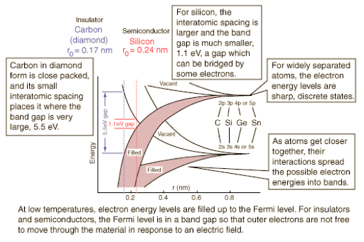
Diagram from hyperphysics (poor link) shows the energy bands for the outermost electrons are qualitatively similar for carbon, silicon, germanium and tin. Though they will differ in detail, the generic band diagram below can show why these materials have different electrical properties.
2 Band theory from wikipedia:
Quantum mechanics states that electrons in an atom cannot take on any arbitrary energy value. Rather, the electrons must occupy fixed energy levels, and values between these levels are impossible. When a large number of such allowed energy levels are spaced close together (in energy-space)—i.e., have similar (minutely differing)—energies, we can talk about these energy levels together as an "energy band." There can be many such energy bands in a material, depending on the atomic number {number of electrons (if atom is neutral)} and their distribution (besides external factors like environmental modification of the energy bands).
The material's electrons seek to minimize the total energy in the material by going to low energy states; however, the Pauli exclusion principle means that they cannot all go to the lowest state. The electrons instead "fill up" the band structure starting from the bottom. The characteristic energy level up to which the electrons have filled is called the Fermi level. The position of the Fermi level with respect to the band structure is very important for electrical conduction: only electrons in energy levels near the Fermi level are free to move around since the electrons can easily jump among the partially occupied states in that region. In contrast, the low energy states are rigidly filled with a fixed number of electrons at all times, and the high energy states are empty of electrons at all times.
In metals there are many energy levels near the Fermi level, meaning that there are many electrons available to move. This is what causes the high electronic conductivity in metals.
An important part of band theory is that there may be forbidden bands in energy: energy intervals that contain no energy levels. In insulators and semiconductors, the number of electrons happens to be just the right amount to fill a certain integer number of low energy bands, exactly to the boundary. In this case, the Fermi level falls within a band gap. Since there are no available states near the Fermi level, and the electrons are not freely movable, the electronic conductivity is very low.
3 Graphene is the ‘new’ version of carbon; a 2-D hexagonal lattice of carbon atoms. See wiki and ManU (the university, not the soccer team). A material of the immediate future. Besides being a better conductor than copper, it is a lot stronger than steel, conducts heat well and is near to transparent. It produces many interesting effects and you can expect to learn some of these in the next decade. Examples: what happens optically when you put a voltage across a sheet? How does it behave under laser light? How small can a piece of graphene be and stay stable? Might we use graphene to lose heat from a chip and at the same time provide components in that circuit? How does it behave in strong magnetic fields? What happens when we dope graphene? If one layer behaves interestingly, what happens with two or more? Might we get something equivalent to polarisation effects? I read we can have nano tubes; so can we make these occur as joints between or within sheets, something like reinforcing bars in steel? If it is 2-D, will it deform to fit a 3-D surface? Is is stable with biology (if so, I imagine it might make a substrate for plastic surgery)? Surely it will make wonderfully fine mechanical filters. Might it produce electrically conductive paint? What I’m saying here is that we’re looking at a material that seems capable of doing several things at the same time; just the idea of that, when we do so much linear thinking, leaves me feeling stimulated.
4 I learned (long ago) reciprocal Ohms to be Mhos. Apparently the term changed in 1971 (liars; not at school, where I was doing A-levels that year). Base units of a siemen or mho would be kg⁻¹m⁻²s³A².
5 Yes, basically. Look up how a fluorescent light works as an example. The light doesn’t cool down enough for you to notice any dimming effect, unless looking at something like a spinning motor, where the strobe effect will show up.
6 [insecure site link fails in 2018 and, in trying to find it I was referred this page on my site. The content seems to be moved to here.
The speed at which electromagnetic effects travel down a wire is called the signal velocity", "the wave velocity", or "the group velocity". Note that some books insinuate that the signal velocity describes a purely electromagnetic wave effect. This insinuation can be misleading. If the signal traveling down an electric cable was an isolated electromagnetic wave, then the signal would travel at the speed of light in vacuum c. But it does not. Rather, the signal traveling down an electric cable involves an interaction of both the electromagnetic field fluctuations (the wave) and the electrons. For this reason, the signal velocity is much faster than the electron drift velocity but is slower than the speed of light in vacuum. Generally, the signal velocity is somewhat close to the speed of light in vacuum. Note that the "signal velocity" discussed here describes the physical speed of electromagnetic effects traveling down a wire. In contrast, engineers often use the phrase "signal speed" in a non-scientific way when they really mean "bit rate". While the bit rate of a digital signal traveling through a network does depend on the physical signal velocity in the wires, it also depends on how well the computers in the network can route the signals through the network.
Consider this analogy. A long line of people is waiting to enter a restaurant. Each person fidgets nervously about in their spot in line. The person at the end of the line grows impatient and shoves the person in front of him. In turn, when each person in the line receives a shove from the person behind him, he shoves the person in front of him. The shove will therefore be passed along from person to person, forwards through the line. The shove will reach the restaurant doors long before the last person in line personally makes it to the doors. In this analogy, the people represent the electrons, their arms represent the electromagnetic field, and the shove represents a fluctuation or wave in the electromagnetic field. The speed at which each person fidgets represents the individual electron velocity, the speed at which each person individually progresses through the line represents the electron drift velocity, and the speed at which the shove travels through the line represents the signal velocity. Based on this simple analogy, we would expect the signal velocity to be very fast, the individual velocity to be somewhat fast, and the drift velocity to be slow. (Note that in physics there is also another relevant speed in this context called the "phase velocity". The phase velocity is more of a mathematical tool than a physical reality, so I do not think it is worth discussing here).
7 Velocity factor VF is that fraction of the speed of light that a signal travels at, expressed as a percentage. See here. if κ is the dielectric constant, then VF = κ-1/2, or if you prefer, κ(VF)²=1. Typical coaxial cable has VF% values of 75 ± 10. The signal velocity, vs = cκ-1/2. I assume that there is no difference between this sort of signal and the speed of the wave-front in any other circuit—I don’t see why there should be. Physicists who can explain this are encouraged to attempt to do so. I note with amusement from wiki: Relative permittivity is also commonly known as dielectric constant, a term deprecated in physics and engineering, but one which is still commonly used in chemistry. For this unit, vacuum is 1 by definition, so water is 88 and silicon about 12. Thus I discover that the white fluffy polyethylene in a coaxial cable is important; using a different material would cause the signal to behave differently.
8 Essay thought: is this evidence that signals might travel very quickly indeed? Might there be occasions where signals go faster than c? http://www.sciencedirect.com/science/article/pii/S0003491602962330 is a starting point.
